How to use Spindle FEA
Spindle FEA application is an easy to use tool that can be run either directly from the command line or from the Abaqus CAE GUI interface. Here we discuss prerequisites and provide a step-by-step guide to running a simple analysis.
Note
If you have any problems running the application or you have any other queries, please email me or raise an issue on GitLab.
Requirements
1. The application relies on the third party finite element package Abaqus CAE by Dassault Systems. Abaqus CAE version 6.11+ should be installed in order to use this application. No further requirements need to be satisfied for a simple use of the application without modifying modules.
2. If, however, the internal modules need to be modified to add some new functionality or alter the existing one it is recommended to install Python 2.7 and Anaconda platform.
Configure and run the analysis
Run executing python scripts in Abaqus CAE graphical interface
- Lunch Abaqus CAE from the command line or shortcut on your desktop and close the
Start Sessionwindow.

- Go to
Fileand toSet Work Directory...

and browse to the root directory of Spindle FEA called Spindle.
- Configure
job.pyfile by providing all the essential modelling parameters. All the spindle geometric and physical parameters should be inserted into a dictionarykwargs. - Modify execution parameters in
mdb.Job()injob.pyfile.
1 2 3 4 5 6 7 | mdb.Job(name=name, model=modelname, description='', type=ANALYSIS, atTime=None,
waitMinutes=0, waitHours=0, queue=None, memory=90,
memoryUnits=PERCENTAGE, getMemoryFromAnalysis=True,
explicitPrecision=SINGLE, nodalOutputPrecision=SINGLE, echoPrint=OFF,
modelPrint=OFF, contactPrint=OFF, historyPrint=OFF, userSubroutine='',
scratch='', resultsFormat=ODB, multiprocessingMode=DEFAULT, numCpus=1,
numGPUs=0)
|
Users may change queueing by changing queue parameter, memory allocation in % by changing memory parameter,
the precision of the computation in explicitPrecision and in nodalOutputPrecision and also request parallelisation of computations
by changing type of threading in multiprocessingMode, number of CPUs in numCpus and number of GPUs in numGPUs. It is highly
recommended that before changing any of the above parameters you closely read the Abaqus CAE documentation accessible from Help tab
in Abaqus CAE graphical interface.
- Run the analysis by going to
FilethenRun Script...and selectingjob.py.

6. After the analysis has been executed you can see the results by opening a Job-1.odb file within Abaqus graphical interface.
The critical buckling loads will also be accessible from Job-1.dat file. If you renamed the job by changing JobName parameter in
job.py file then the .odb and .dat files will have different names.
Run from Windows or Linux command line
- To run the job from the command line you should first navigate to
Spindledirectory usingcdcommand.
2. Within Spindle directory, you need to open job.py in your favourite code editing application if you want to
change some default parameters of the analysis.
- When ready you need to type
abaqus cae noGUI=job.pyin the command line and hit enter to start the analysis. - After the analysis has finished you can open
Job-1.odbin Abaqus GUI or access it via your own python scripts. Same for theJob-1.datfile.
Explanation of the kwargs parameters
The default kwargs dictionary is presented in the code snippet below. The defaults may be
easily changed by replacing the values of kwargs in job.py with the user-defined ones.
1 2 3 4 5 6 7 8 9 10 11 12 13 14 15 16 17 18 19 20 21 22 23 24 25 26 27 28 29 30 31 32 | " User input parameters "
kwargs =
{'x' : 0,
'y' : 0,
'index' : 0,
'modelname' : 'test',
'assembly' : 0,
'CentrosomeRadius': 0.12,
'CentrosomeLength': 0.24,
'CentrosomeE' : 1500000000.0,
'CentrosomeNu' : 0.3,
'ipMTnumber' : 6,
'lengthInterval' : [2, 5],
'separation' : [0.02876, 0.0414],
'angle' : [96.39, 11.12],
'd' : 0.015,
'D' : 0.025,
'ElasticModulus' : 1500000000.0,
'PoissonRatio' : 0.3,
'spindleLength' : 10,
'Nconnectors' : 10,
'connectorRadius' : 0.005,
'connectorE' : 1500000000.,
'connectorNu' : 0.3,
'aMTnumber' : 20,
'aMTlength' : 2,
'aMTsSpring' : 10,
'groundSpring' : 10,
'StepName' : 'Standard_Buckling',
'NumberOfEigs' : 5,
'CompressiveLoad' : 1,
'JobName' : 'Job-1'}
|
Here modelname is the string representing the name of the model,
CentrosomeRadius is a radius of the centrosome or pole in \(\mu m\).
CentrosomeLength is a length of the centrosome or pole in \(\mu m\).
CentrosomeE is an elastic modulus of centrosome material in \(\frac{pN}{\mu m^{2}}\).
CentrosomeNu is a Poisson ratio of the centrosome material. Taken to be \(0.3\) for the isotropic model.
ipMTnumber is a number of inter-polar microtubules in a bundle. Typically up to \(6\) in Anaphase B.
lengthInterval is defined by the mean value of the Gaussian distribution \(\mu_{L} = 5 \mu m\) representing the average length of the inter-polar microtubule \(L_{p}/2\) and the standard deviation \(\sigma_{L} = 2 \mu m\) of the MT length \(L_{m}/2\).
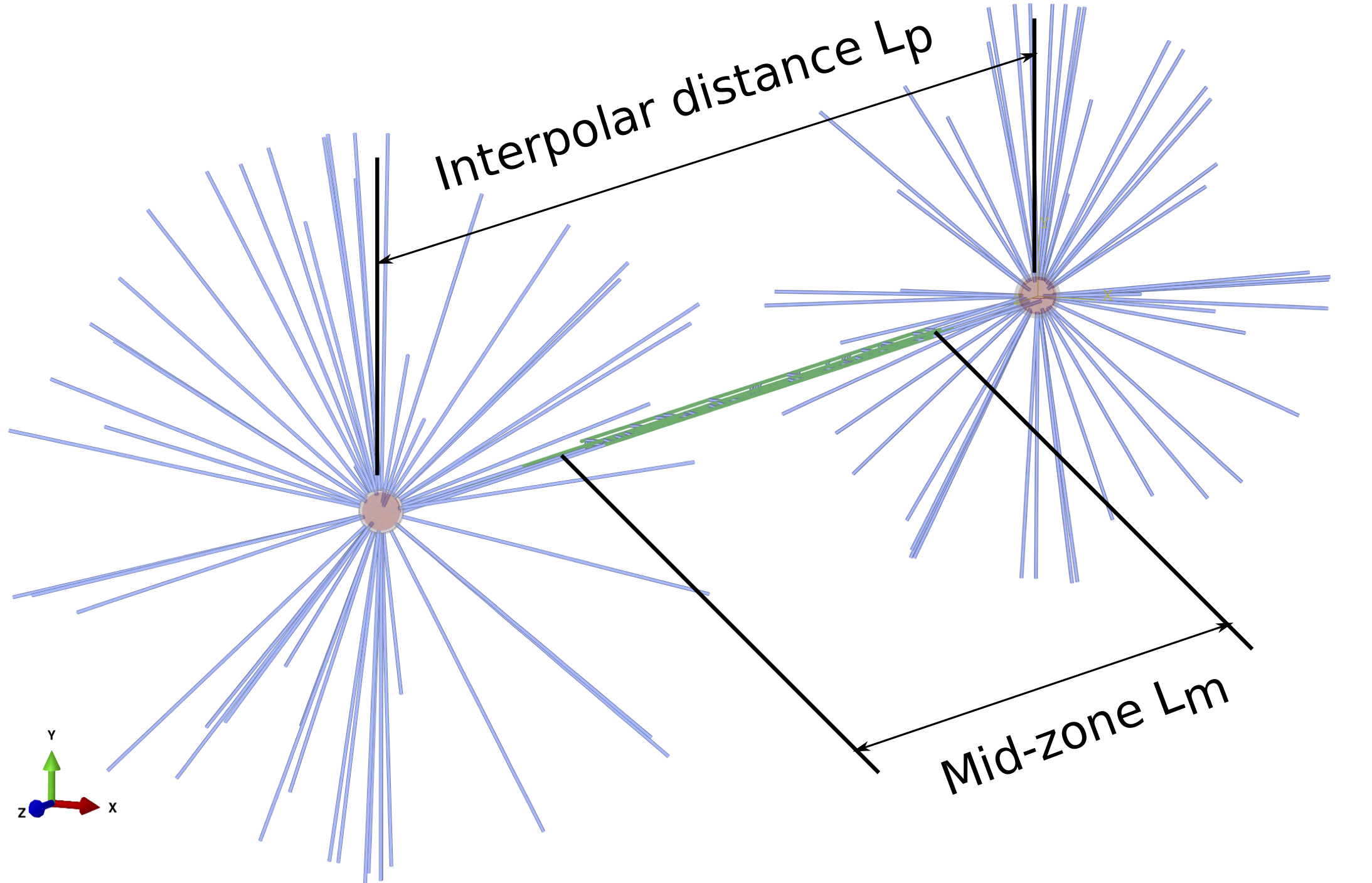
The model of the whole spindle in anaphase B generated by Spindle FEA with the interpolar distance labelled \(L_{p}\) and the midzone length labelled \(L_{m}\).
The inter-polar distance is the distance between the centrosomes \(L_{p}\) and the midzone length is the length \(L_{m}\) of the zone where MTs are coupled by cross-linkers and protein motors as shown in Fig. 1.
separation is the distance between two neighbouring MTs in the inter-polar bundle as shown on the cross-sectional view of the spindle in Fig. 2.
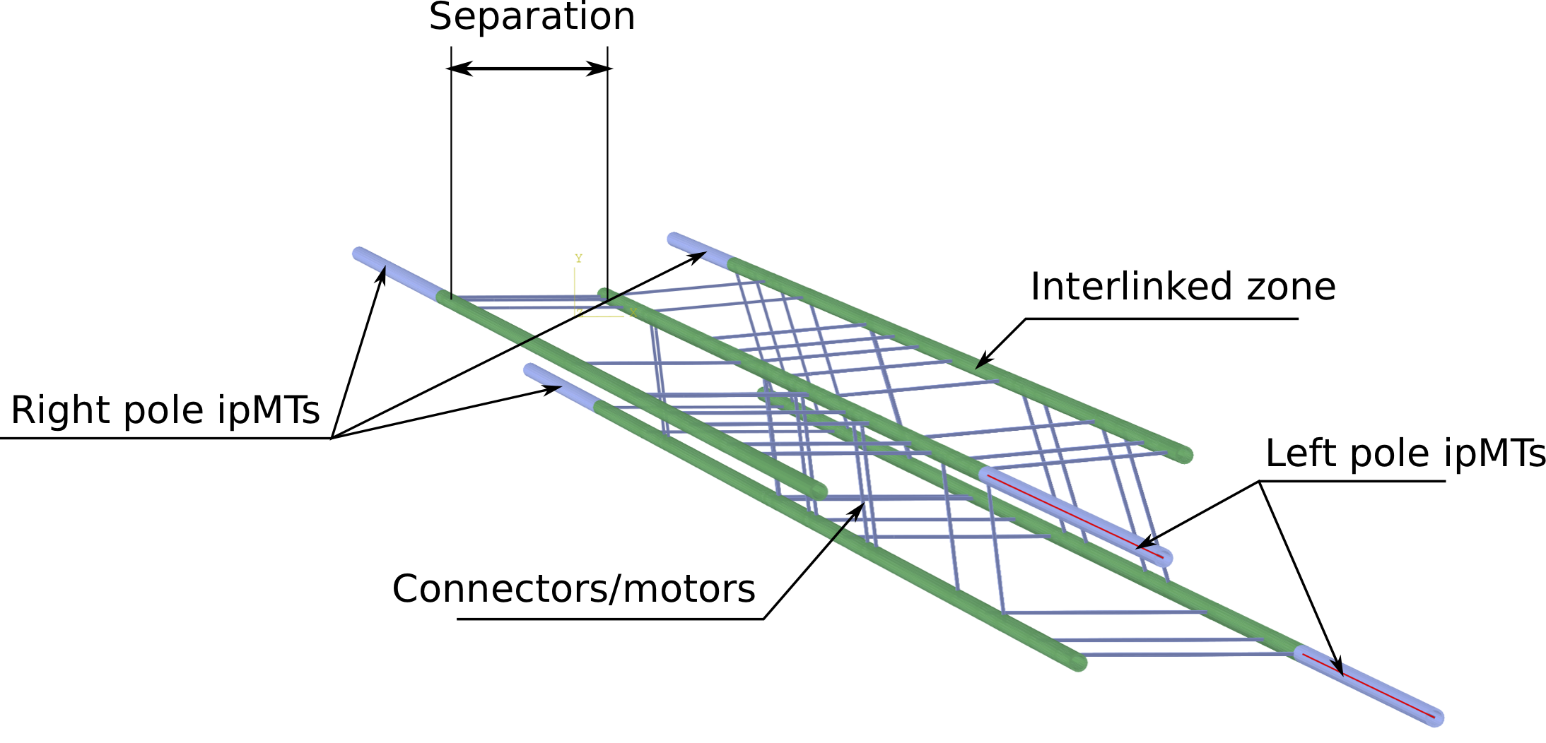
The model of the inter-polar bundle of the mitotic spindle generated by Spindle FEA exhibiting right and left pole MTs, interlinked zone, connectors and protein motors as well as the separation distance between MTs in a bundle.
It is generally random and by default is defined by the Gaussian distribution with \(\mu_{s} = 0.02876 \mu m\) and \(\sigma_{s} = 0.0414 \mu m\) that were calculated from the experimental data [1].
angle is the the orientation angle \(\phi\) of the microtubules within the inter-polar bundle as shown in Fig. 3.
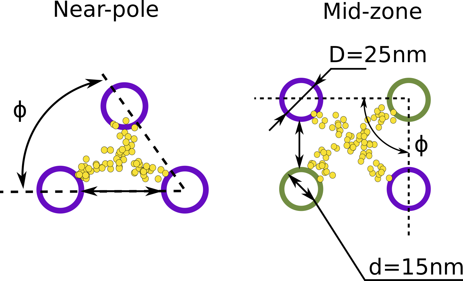
The schematic view of the cross-section of the inter-polar bundle of microtubules near-pole and in the mid-zone. The green MTs are growing from the left pole while the purple ones are growing from the right pole.
The MT angle is also defined by a Gaussian distribution with mean and standard deviation taken from experimental data [1]. The default values are \(\mu_{\phi}=96.39^{\circ}\) and \(\sigma_{\phi}=11.12^{\circ}\).
d is the inner diameter of a microtubule as shown in Fig. 3. Default value is \(d=0.015 \mu m\).
D is the outer diameter of a microtubule as shown in Fig. 3. The value is \(D=0.025 \mu m\) according to Ward et al. [2] and \(D=0.018 \mu m\) according to Pampaloni et al. [1] The default value is \(D=0.025 \mu m\).
ElasticModulus is an elastic modulus of microtubule material. In the simplest case of the isotropic model for microtubule is assumed and the default value is \(E=1.5 \times 10^{9} \frac{pN}{\mu m^{2}}\) [2].
PoissonRatio is the Poisson ratio of microtubule material. Assumed to be \(\nu=0.3\) for the isotropic model.
spindleLength is the distance between poles of the spindle as shown in Fig. 1. The default value for the late anaphase B is \(L_{p}=10 \mu m\) [1].
Nconnectors is the number of cross-linkers and protein motors in the mid-zone (see Fig. 2). The exact number of cross-linkers is hard to estimate from the experiments, therefore, it can become
one of the governing parameters of the model. The default value is \(10\) per microtubule.
connectorRadius is the radius of the cross-link between MTs. The default value is \(r=0.005 \mu m\).
connectorE is the elastic modulus of the connector material. The default value is assumed the same as the one for the microtubule \(E=1.5 \times 10^{9} \frac{pN}{\mu m^{2}}\).
connectorNu Poisson ratio of the connector material. Assumed \(\nu=0.3\).
aMTnumber is the number of astral microtubules to be modelled in a spindle. The default is \(20\).
aMTlength is the length of astral MTs which is generally governed by the radius of the cell membrane and the length between cell tips. The default value is \(L_{aMT}=2 \mu m\) with cell radius \(R_{cell}=1.6 \mu m\) [1] and the cell length \(L_{cell}=14.3 \mu m\) [1].
aMTsSpring is the stiffness of the distributed spring that we employ to model astral microtubule embedding in the surrounding mesh of MT connectors [3]. The default value is \(k = 10 \frac{pN}{\mu m^{2}}\).
groundSpring is the spring stiffness of the distributed spring that we employ to model inter-polar MT bundle embedding in the mesh of MT connectors [3]. The default value is \(k = 10 \frac{pN}{\mu m^{2}}\).
StepName is the name of the buckling analysis step.
NumberOfEigs is the number of the eigenvalues and, thus, critical buckling loads that need to be calculated. Notice, that as buckling analysis uses subspace algorithm for eigenvalue calculation the execution time will increase dramatically with the number of requested eigenvalues.
The default is 5.
CompressiveLoad is the preload factor that will be used to multiply the eigenvalue to obtain the critical buckling load. It is recommended that this parameter is not changed.
JobName is the name of the job and will be included in all the names of all files produced by analysis. The default is Job-1.
[1] (1, 2, 3, 4, 5, 6) J. J. Ward, H. Roque, C. Antony, and F. Nedelec. Mechanical design principles of a mitotic spindle. eLife, 2014.
[2] (1, 2) F. Pampaloni, G. Lattanzi, A. Jonas, T. Surrey, E. Frey, and E-L. Florin. Thermal fluctuations of grafted microtubules provide evidence of a length-dependent persistence length. Proceedings of the National Academy of Sciences, 2006.
[3] (1, 2) F. M. Nixon, C. Gutierrez-Caballero, F. E. Hood, D. G. Booth, I. A. Prior, and S. J. Royle. The mesh is a network of microtubule connectors that stabilizes individual kinetochore fibers of the mitotic spindle. eLife, 2015.
